2009 Entry Gate Project
2009 Entry Gate Project
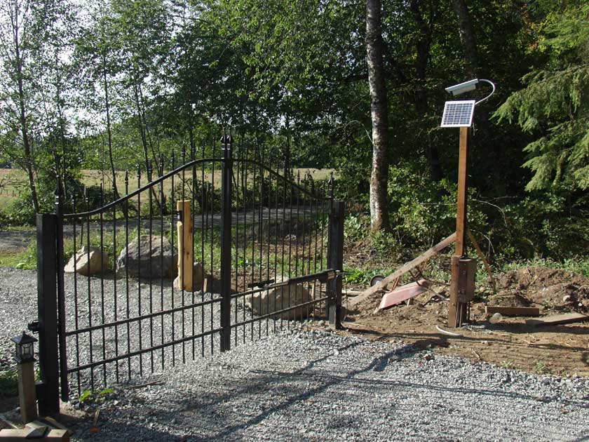
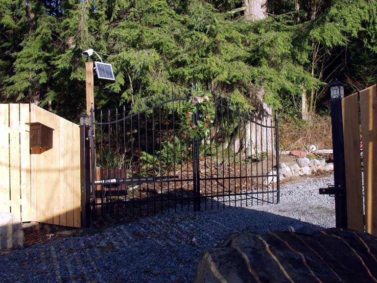 Gate with fencing Note the black box with magneto phone inside |
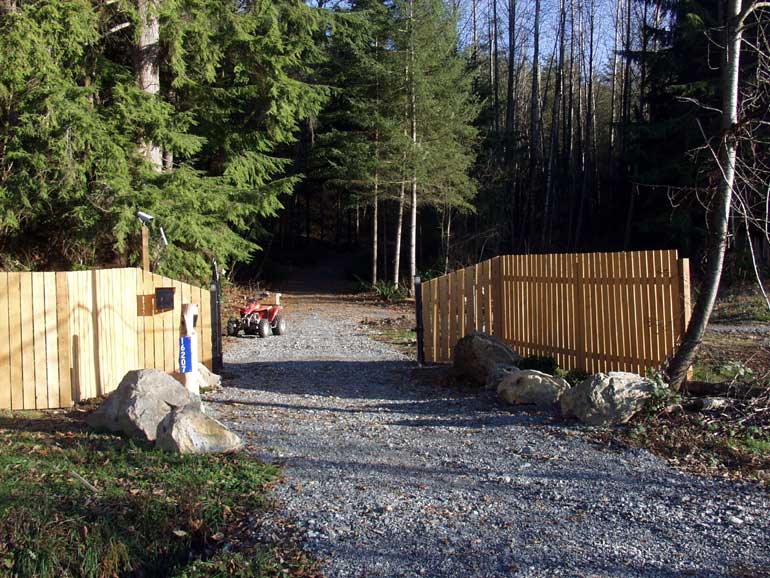 Wide shot of gate |
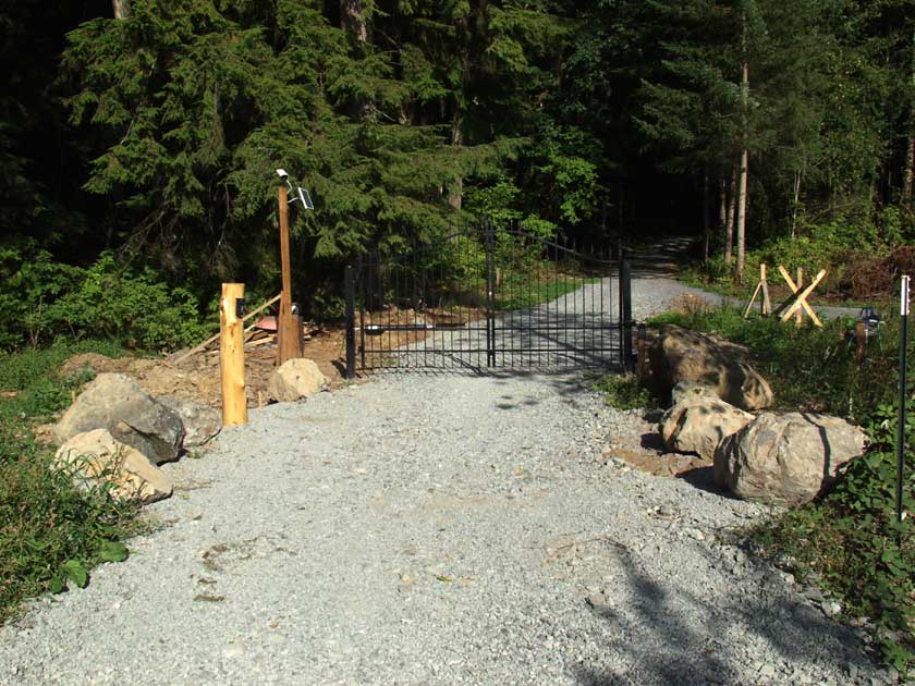 View of completed gate from the road before fencing |
 Back side of gate |
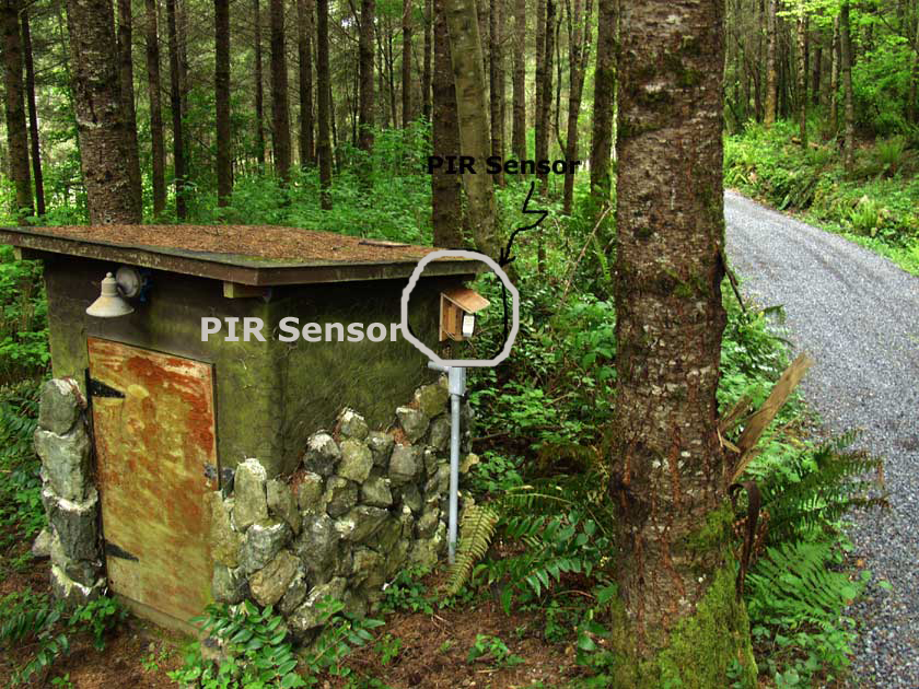
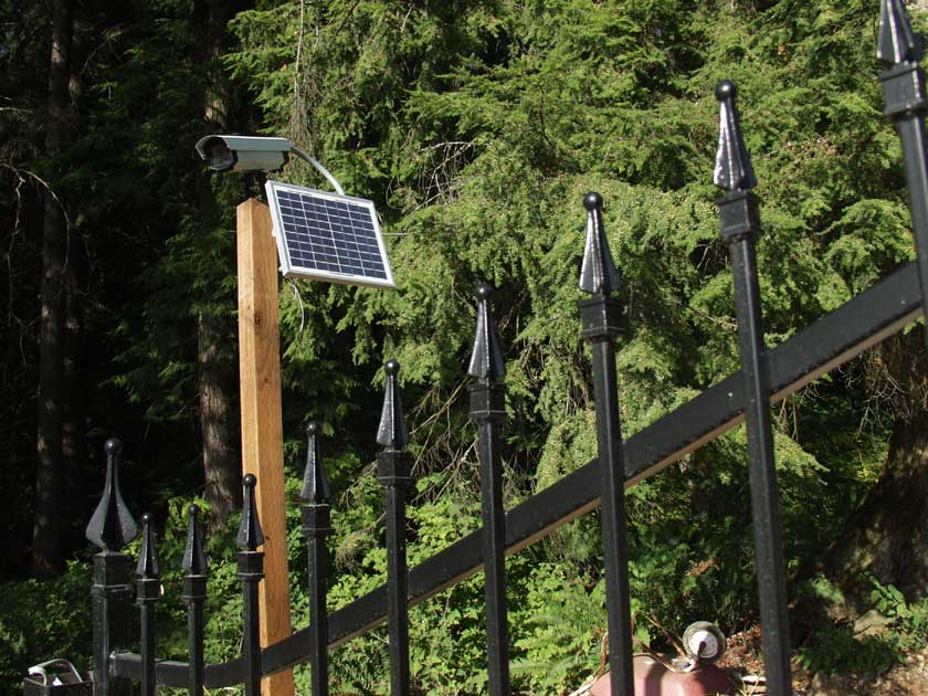 Shot of the camera and solar cell array. So far the solar cells are keeping the gate batteries charged and there is no connection to the 115 Volt power. |
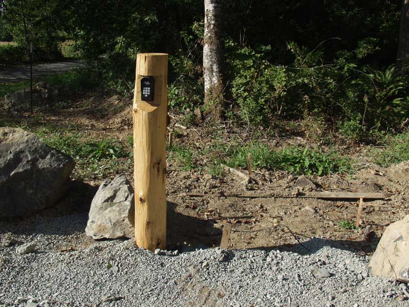 Combination entry keypad on cedar post |
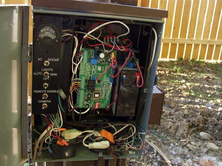 Gate Control box Interior Note the battery voltmeter at the top of the Left Hand panel.. Gives an idea of the battery condition and solar power efficiency. 12 Volt gel-cel on right side and gate control board in the middle. Also switches for camera power, AC or Solar, gatepost lights photocell automatic or manual control, switch to disable remote operation of the gate from the house.
|
|
 1940 Leich Magneto Phone at Gate Connects to house and is a part of the Valhalla "Local Battery" private telephone system. More on the Valhalla Phone System Instruction card states to vigorously turn the magneto crank for six rings and listen for an answer. Gate control from house opens gate when caller is identified over phone and video. More on Valhalla video surveillance |
|
|
|
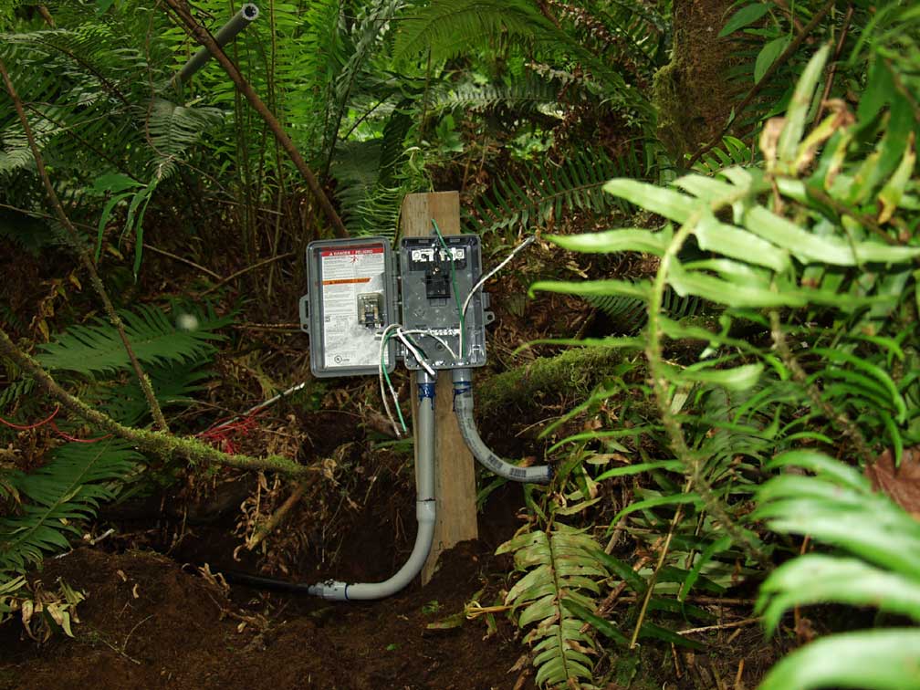
 Here's Dave putting the finishing touches on the junction box. It was painted flat brown upon completion.
|
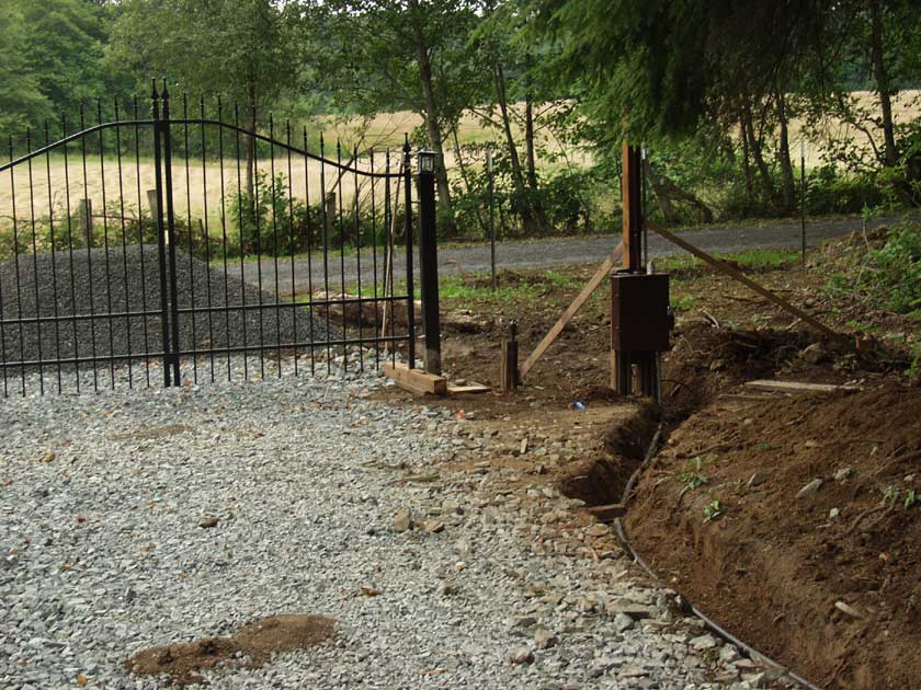 Shot of the conduit run to the exit sensor wand before backfill of the ditch. Note the 4 yards of gravel ready to be spread. |
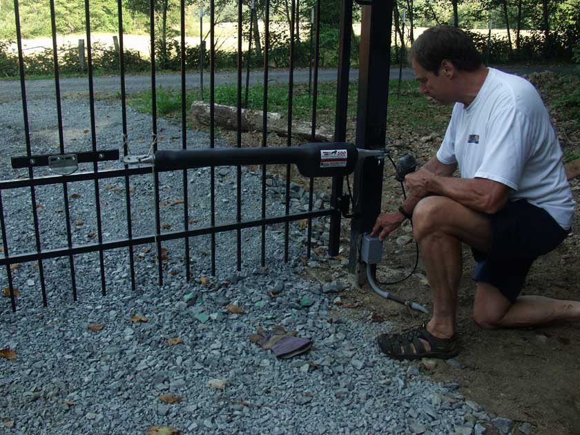 Here's Dave doing the initial hookup and mounting check of the "Mighty Mule" Gate actuator |
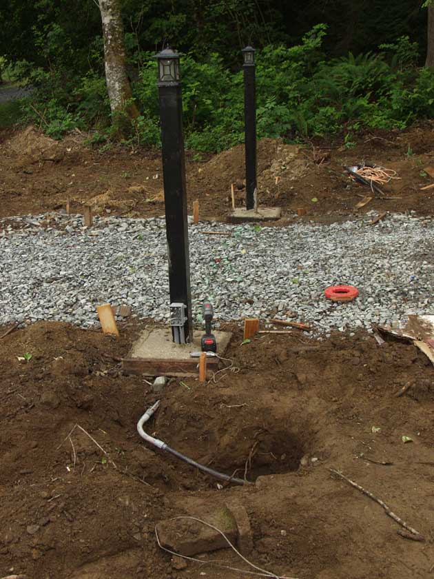
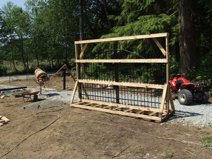 Gate in it's "crate" as final preparations are made to make sure the layout is correct and pour the post concrete. |
 Final check of the dimensions and plumb of the posts. |
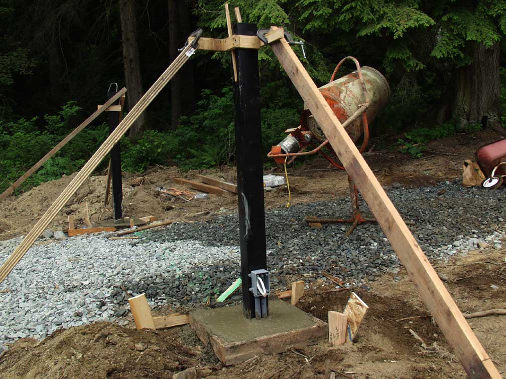 Wet concrete and we hope all measurements are correct. Electric mixer is the only way to go! |
|
|
|
|
|
|
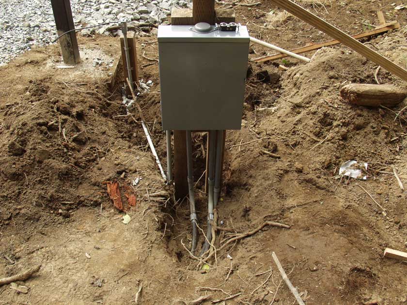
Shot of one of four power junction boxes along the 500
ft driveway. |
|
|
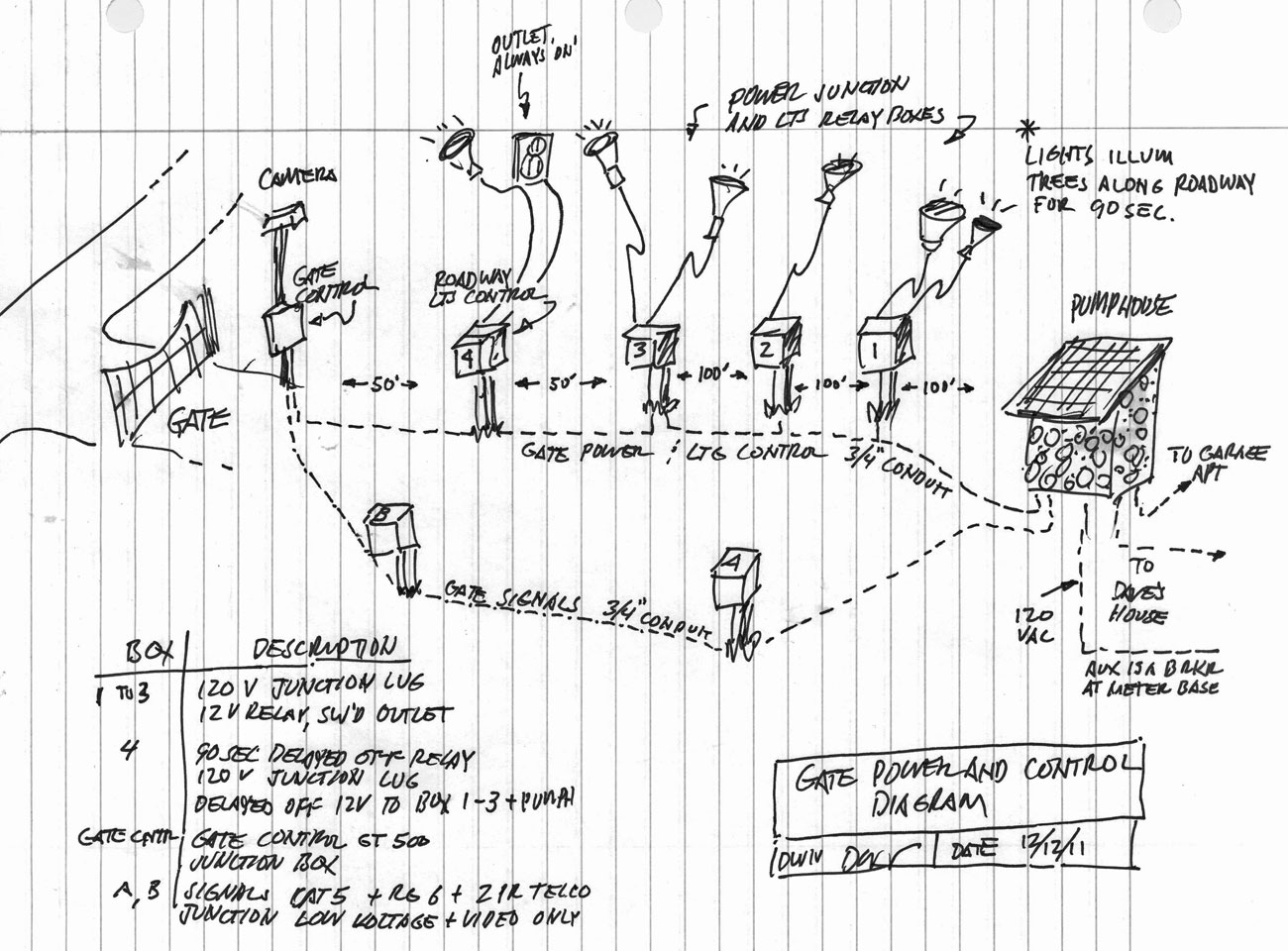
 Wiring diagram for the driveway floodlight system lower control box. System actuation begins with sensing of the motor power on the gate. This pulls in a 2 minute time delay relay which sends 12 volts up the control pair. Each junction box then receives the 12 volt power and turns on its floodlight until the time is up and they all switch off. |
|
|
![]()

1-14-12